Servo Actuated Nozzle Brush and Purge Bucket - Post 1
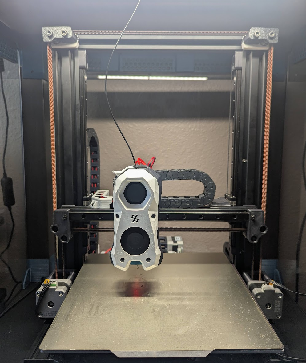
I am currently in a high-project-motivation period where my 3d printer is seeing alot of use, and one deficiency I need to address is my pre-print routine. Currently I use the classic creality purge line; this works well for purging the nozzle itself, but during preheat a stray blob or string of filament will usually end up sticking to the nozzle exterior. This stray filament has a tendency to not get wiped off on the purge line and will end up somewhere in the middle of my first layer. I picked up a pack of cheap servos and some silicone nozzle brushes to try to find a solution. This is also a good way for me to start getting into the weeds of extending printer functionality with klipper.
Initial Design
I will be using a generic sg90 servo to drive the assembly. The initial design uses a parallel four-bar linkage for motion. If you reduce the assembly to a two dimensional drawing, the forces from the nozzle should all be in the plane of motion. The assembly will mount to one of the longitudinal side frame rails. I originally wanted to fit the assembly on the x gantry somewhere, but the core x-z belts leave me little room to work with. I threw together a quick cad assembly as proof of concept. Per the limited motion analysis I performed, the assembly should work with no interference. I printed out a prototype to see if the assembly would perform just as well in the real world.
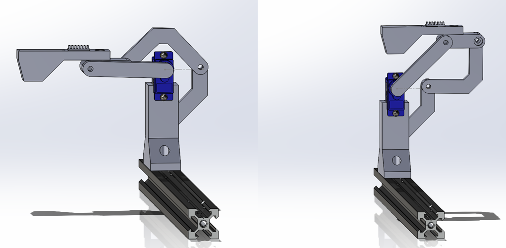
right: stowed configuration
The First Prototype
While the CAD model works perfectly, the actual prototype revealed a few problems with the design. Currently the pivots are just through holes sitting on m3 screws, which introduces alot of slop. The sg90 servo also has a bit of backlash in the gear train. With the provided horn the backlash isn’t very noticable, but the 50mm long input link magnifies the backlash effects.
One significant problem is in the deployed configuration. As the assembly needs to reach over the bed when deployed, I wanted the deployed position to have as much reach as possible. I designed the assembly so that when deployed, the input link is at 0° and all the links are in line. Although this gives a good amount of reach, the coupler link holding the nozzle brush is easily pushed over center and ruins the kinematics.
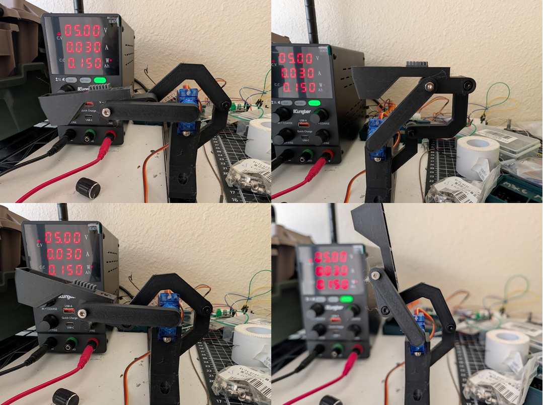
bottom: flipped link stowage
Even with the hardware tightened down, there is unwanted movement of the brush/coupler link when force is applied. Although I am planning to use brass sleeve bushings for the final assembly, this play in the brush end may be unavoidable given the amount of backlash in the servo gear train.
Redesign
To avoid the backlash of the servo while the nozzle is wiping against the brush, I will redesign the assembly so the plane of motion is normal to the nozzle pushing downwards on it. I will also design the deployed position to have the two pairs of links perpendicular to each other to hopefully mitigate the over center issue. As the nozzle will only be wiping in the x direction, the input link should be in line with the x axis when deployed. I will also need to design a way for the links to be supported from the bottom.